Hollow Pin Geometry, Cross Rods & Attachments
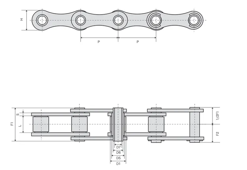
Plan hollow pin chain cross rods, carriers, slats, fixtures and attachment hardware around bore size, span, fastening and conveyor clearance.
What the hollow pin gives you
A hollow pin creates a through-hole at each chain joint. Machine builders can use that opening to locate a rod, bolt, spacer or custom attachment without relying on a permanently extended pin. The attachment can support carriers, slats, pushers, guides or fixtures depending on the machine.
Bore and clearance
Do not make the attachment diameter equal to the nominal bore. Allow the clearance needed for assembly, coating, contamination and service. Also check whether the rod should rotate in the pin or remain fixed, because that changes the wear point and retaining method.
Cross rods between two strands
When one rod connects two chains, chain center distance and strand synchronization become important. A long or offset-loaded rod can bend, while a skewed carrier can pull one chain ahead of the other. Provide the rod diameter, span, fixture weight and load position with the RFQ.
Retaining the attachment
Common concepts include nuts, clips, collars, spacers and custom end hardware. The best method depends on service access, vibration, hygiene requirements and whether the attachment needs frequent removal. Show any critical side-frame clearance on the drawing.
Through the sprocket turn
Check that the attachment and retaining hardware clear the sprocket, shaft, frame and guide as the chain articulates around the end of the conveyor. A straight-run drawing can look correct while the same hardware interferes during sprocket engagement.
Buyer checklist
- Hollow bore and proposed attachment diameter
- Rod span and chain center distance
- Carrier weight and product load position
- Fastening or retaining method
- Sprocket and side-frame clearance
- Cleaning and service-access requirements
Send your chain details for review
Include the model or dimensions, attachment drawing, sprocket information, speed, load, environment and quantity for a quotation.
Read the chain drawing from the machine outward
Pitch establishes where each potential attachment point repeats. Hollow bore determines the maximum rod or fastener that can pass through the pin. Inner width and roller or bush diameter define the sprocket and guide interface. Side-plate height and overall pin projection define the external envelope available inside the machine.
| Dimension | Machine question | Common risk if omitted |
|---|---|---|
| Pitch | Does it match the sprocket and carrier interval? | Wrong engagement or station spacing |
| Hollow bore | Will the rod fit with usable clearance? | Forced assembly or redesign |
| Inner width | Does the sprocket fit between inner plates? | Binding and side wear |
| Roller/bush diameter | Where does the chain contact the guide? | Wrong running height |
| Pin projection | Is there room for retention hardware? | Guard or frame interference |
Cross rods create a second load path
A rod connecting two chains transfers load between strands and can introduce bending. Provide the distance between chain centrelines, rod diameter, rod material, product or fixture load and any overhung load outside the chain. A wide, slender rod can deflect enough to pull the chains sideways even when the conveyor load seems light.
Choose a retention method that can be serviced
The rod or fixture must stay in place during acceleration and vibration but also remain accessible for maintenance. Retention can be designed with shoulders, clips, threaded features or other hardware depending on the machine. The important point for chain selection is to show the final outside envelope and confirm that the retention hardware clears sprockets, guides and guards.
Matched strands and carrier squareness
When a rigid carrier bridges two chain strands, differences in effective chain length can skew the carrier. If the application requires matched strands, state it in the RFQ and keep the two chains identified as a set during installation. Equal shaft alignment and guide friction are also necessary; matched chain cannot compensate for a mechanically misaligned conveyor.
Replacement measurement method
Clean the old chain enough to expose the joints and measure several pitches under light tension. Divide the total by the number of pitches to estimate nominal pitch. Measure hollow bore, inner width, roller or bush diameter, plate height, thickness and total outside width. Photograph the chain beside a scale and separately photograph the sprocket and guide. If a machine drawing is available, note which dimensions came from the drawing and which were measured from worn parts.
Attachment drawing checklist
- Chain model or intended series
- Rod or fastener diameter
- Rod material
- Strand centre distance
- Unsupported rod span
- Carrier mass and offset
- Retention hardware envelope
- Required attachment spacing
Allow for assembly clearance without creating excessive play
The rod passing through a hollow pin needs practical assembly clearance, but too much clearance can allow impact or fretting. The appropriate fit depends on rod material, retention method, contamination and whether the part is removed regularly. Put both nominal rod diameter and hollow-bore requirement on the drawing instead of relying on a verbal “loose fit.”
If the rod is threaded, shouldered or carries a clip outside the chain, include those outside dimensions. The chain may fit the sprocket while the retention hardware still collides with a frame or guide.
For a carrier mounted at every second, third or fourth pitch, mark the attachment sequence explicitly. This prevents an otherwise correct chain from being assembled with the wrong fixture spacing. If connecting links or special end arrangements change the sequence, include those details in the finished-length drawing.
Where tolerances are critical, place them on the attachment drawing rather than assuming a catalogue dimension controls the finished assembly. The chain and rod should be inspected against the dimensions that actually affect machine fit.